MHK Turbine Applications
RAFT can also suport underwater marine hydrokinetic (MHK) turbines. Just as with floating wind turbines, RAFT can support the frequency-domain modeling of the global response and linearized controlled rotor dynamics of a moored, floating MHK turbine system.
This page provides information on how to use the MHK capabilities of RAFT and how the features are applied to the existing model.
New Features
To model underwater MHK systems, we have added the following new features to the model:
Rotor buoyancy
Multiple rotors with arbitrary positions and attachments
Rotor added mass
Fluid inertia excitation on rotor
Rotor gyroscopic reactions
Cavitation check
Blockage effects
Mean current drag loads on floating structure
Set Up
Hub Height
In an input file for a MHK device, the one thing that must be done is to ensure that the ‘hHub’ input is set to a negative number. This ensures that all the MHK features can be turned on.
turbine:

    hHub         : -25.2
Environmental Inputs
It is also recommended to set the environmental variables needed for MHK calculations. If not, defaults will be set.
site:
    water_depth : 60         # [m]      uniform water depth
    rho_water   : 1025.0     # [kg/m^3] water density
    rho_air     : 1.225      # [kg/m^3] air density
    mu_air      : 1.81e-05   #          air dynamic viscosity
    shearExp_air: 0.12       #          wind shear exponent
    mu_water    : 1.00e-03   # [kg/ms]  water dynamic viscosity
    shearExp_water : 0.12    #          current shear exponent
The cases dicionary needs to contain current information if it did not already if the hub height is negative. The wind speed parameters do not matter. When the hub height is set to a negative number, RAFT then looks to the current information as turbine inflow parameters. Non-rotor wind loads are not supported yet.
cases:
    keys : [wind_speed, wind_heading, turbulence, turbine_status, turbine_heading, wave_spectrum, wave_period, wave_height, wave_heading, current_speed, current_heading, current_turbulence  ]
    data :  #   m/s        deg    % or e.g. IIB_NTM    string            deg         string          (s)          (m)          (deg)         (m/s)           (deg)         % or e.g. IIB_NTM
        -  [    0.0,        0,            0,         operating,          0,           JONSWAP,        8.0,        2.0,           0,           1.9,             0,                  0          ]
Multiple Rotors
The number of rotors in the Model can also be specified by an integer value, with coordinates of each rotor defined as the coordinates in the x-y plane if there was no overhang. If coordinates of [0,0] are specified, then the rotor hub will be located at (x,y,z) = (overhang, 0, hHub)
turbine:

    nrotors     :  1                # [-]        number of turbines in the FOWT
    rotorCoords : [[0, 0]]          # [m, m]     x-y coordinates of rotor in space
Blockage
RAFT can represent blockage from any source (multiple rotors, site boundaries, etc.) using a speed_gain parameter, which only scales the inflow speed seen by the rotor. RAFT does not do any calculation into what the speed_gain would be based on certain blockage scenarios–it only provides a user-defined blockage scaling factor.
turbine:

    speed_gain  : 1.0               # [-]    multiplier on inflow velocity due to flow confinement
Rotor Added Mass
The airfoils of a MHK turbine also require added mass coefficients. RAFT represents the airfoils and blades as a series of rectangular members where each side of the rectangular member can have its own drag and added mass coefficient. When setting up the blade rectangular members, we assume that:
flapwise refers to the direction of movement perpendicular to the blade’s surface, as well as the rotor plane
edgewise refers to the direction of movement in the rotor plane along the blade’s leading and trailing edge
Therefore, we can set added mass coefficients of the airfoils in the design dictionary in the order of [flapwise, edgewise] to correspond to the proper directions of the blade members, as follows:
airfoils:
  - name               : S1  # NACA6_1000
    relative_thickness : 0.9956  #
    added_mass_coeff   : [0.7, 0.7]     # [flapwise, edgewise]
    data:  #  alpha       c_l         c_d         c_m         cp_min
      - [  -180.00,       0.0,        0.7,        0.0,        -3.0 ]
      - [     0.00,       0.0,        0.7,        0.0,        -3.0 ]
      - [   180.00,       0.0,        0.7,        0.0,        -3.0 ]
  - name               : S2  # NACA6_0864
    relative_thickness : 0.8572  #
    added_mass_coeff   : [0.7, 0.7]     # [flapwise, edgewise]
    data:  #  alpha       c_l         c_d         c_m         cp_min
      - [  -180.000,    0.0000,     0.5765,       0.0,       -2.6421]
      - [  -170.000,    0.0727,     0.5765,       0.0,       -2.6421]
      - [  -160.000,    0.1455,     0.5865,       0.0,       -2.6421]
      - ...
For blades, we are assuming that the longer side length (flapwise) corresponds to the p1 direction (conventionally along the x-axis), while the shorter side length (edgewise) corresponds to the p2 direction (conventionally along the y-axis).
However, if we were to set a separate, vertical foil-like member with the leading edge oriented parallel to the flow, we would set the order of added mass coefficients to [edgewise, flapwise].
The drag coefficients of the blades are handled by a separate operation that is included in the conventional calcAero process from CCBlade.
If added mass coefficients are not set, they will default to [0.5, 1.0]. They will not be used if the rotor hub height is positive.
Nacelle Members
RAFT can now support nacelle members that are only used for buoyancy and hydrodynamics. A nacelle member does not contribute anything to the RNA properties–all the RNA mass and inertial properties should be included how they normally are by RAFT. RAFT does however add the additional nacelle member to the end of the memberList, right after the tower member, and includes it in all the normal buoyancy and hydrodynamic calculations.
turbine:

    nacelle:
        dlsMax      :  2.0                        #          maximum node splitting section amount; can't be 0
        name        :  nacelle                    # [-]      an identifier (no longer has to be number)
        type        :  1                          # [-]      type (used for platform members vs. other members)
        rA          :  [4.5478, 0, -25.2]         # [m]      end A coordinates
        rB          :  [-3.6878, 0, -25.2]        # [m]      end B coordinates
        shape       :  rect                       # [-]      circular or rectangular
        gamma       :  0.0                        # [deg]    twist angle about the member's z-axis
        stations    :  [ 0, 1 ]                   # [- or m] location of stations along axis. Will be normalized such that start value maps to rA and end value to rB
        d           :  [1.9529036540547544, 2.4]  # [m]      diameters if circular or side lengths if rectangular (can be pairs)
        t           :  0.06791876744511316        # [m]      wall thicknesses (scalar or list of same length as stations)
        Cd          :  0.0                        # [-]      transverse drag coefficient       (optional, scalar or list of same length as stations)
        Ca          :  0.0                        # [-]      transverse added mass coefficient (optional, scalar or list of same length as stations)
        CdEnd       :  0.0                        # [-]      end axial drag coefficient        (optional, scalar or list of same length as stations)
        CaEnd       :  0.0                        # [-]      end axial added mass coefficient  (optional, scalar or list of same length as stations)
        rho_shell   :  8500                       # [kg/m^3] material density
RAFT Implementations of New Features
Some of the implementation of the new features can be inferred from the set up, but others are explained here:
Rotor Features
When the hub height is set to a negative value, RAFT automatically generates a ‘bladeMemberList’, which is a separate list of RAFT members that define the blade geometry and are used to calculate rotor buoyancy. A series of rectangular members are created with the proper side lengths that correspond to interpolated values of the airfoil chords and thicknesses, as well as twist angles.
The mass of the blades are not included in the conventional mass and inertia calculations, as these masses still remain in the RNA section (same implementation as the nacelle member).
The rotor added mass and fluid inertia excitation are calculated in the same way as other RAFT members (using the input added mass coefficients).
Multiple rotors can be added and their interference is only controlled by the speed_gain blockage scaling factor. Otherwise, RAFT assumes no other hydrodynamic effects between multiple rotors.
Rotor Gyroscopic Effects
RAFT now includes a gyroscopic damping term in its equations of motion, which is a function of the moment of inertia of the drivetrain and the angular velocity vector of the rotor as it is operating. Note that the gyroscopic effect is purely rotational so no translation adjustment is needed.
Cavitation
RAFT also can calculate cavitation along a blade. It simply calls a function that calculates the worst-case cavitation for a given condition, saves the cavitation output in the RAFT output dictionary, and raises a warning message in Python if the cavitation is negative.
Drag
RAFT now has methods to properly calculate a static, mean drag force on the entire floating structure (outside of the hydrodynamics). It takes the drag coefficient of each member, the water velocity at each node, and the geometry of the member to calculate a mean drag force on the platform.
The drag term of Morison’s equation is handled separately.
The static, mean drag on the blades is included in the forces that CCBlade outputs, which is why the drag coefficients of the blade members are set to zero.
Drag on mooring lines is not conventionally included, but work is in progress on properly integrated a quasi-dynamic mooring model.
Reference Current Velocity
The input current speed to the cases dictionary conventionally refers to the current speed at the water surface. For a MHK system, this input current speeds defaults to the speed that the rotor is designed to experience, at the proper hub depth. RAFT accounts for this difference when calculating drag forces on the floating structure.
Example MHK Turbine Case
An example MHK turbine case has been added to the designs included in RAFT.
The figure below is generated by RAFT and shows the calculated system equilibrium state in its loaded condition (produced using the Model.plot method).
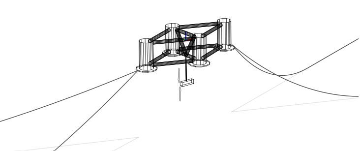
As with FOWTs, properties like natural frequencies and mode shapes can be calculated.
The plot below shows the power spectral densities of select responses calculated from a basic load case (produced using the Model.plotResponse method).
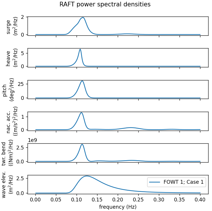
The table below shows the corresponding response statistics:
Response channel |
Average |
RMS |
Maximum |
Minimum |
|---|---|---|---|---|
surge (m) |
3.70e+00 |
2.53e-01 |
4.46e+00 |
2.94e+00 |
sway (m) |
-6.82e-02 |
4.79e-04 |
-6.68e-02 |
-6.97e-02 |
heave (m) |
1.51e-01 |
2.91e-01 |
1.02e+00 |
-7.22e-01 |
roll (deg) |
1.17e-01 |
4.12e-03 |
1.30e-01 |
1.05e-01 |
pitch (deg) |
-1.04e+00 |
7.99e-01 |
1.36e+00 |
-3.44e+00 |
yaw (deg) |
-2.71e-02 |
7.36e-04 |
-2.49e-02 |
-2.93e-02 |
nacelle acc. (m/s) |
1.78e-01 |
1.92e-01 |
7.54e-01 |
-3.99e-01 |
tower bending (Nm) |
-1.05e+07 |
8.35e+03 |
-1.05e+07 |
-1.05e+07 |
line 1 tension (N) |
9.95e+05 |
9.91e+04 |
1.29e+06 |
6.98e+05 |
line 2 tension (N) |
1.00e+06 |
1.00e+05 |
1.30e+06 |
7.03e+05 |
line 3 tension (N) |
1.83e+05 |
4.93e+03 |
1.98e+05 |
1.68e+05 |
line 4 tension (N) |
1.84e+05 |
4.99e+03 |
1.99e+05 |
1.69e+05 |